
DWIN display Ender 3v2 · Issue 40 · bigtreetech/BIGTREETECHSKRE3Turbo · GitHub
Looking for a PCB Layout/Wiring Diagram/Pin Numbering Diagram for the Creality 3D Universal LCD 12864 3D Printer Display Screen With Encoder For Ender-3/CR-10/CR-7 Model. I've checked the GitHub Repositories for the Ender 3 and can't find anything other than the mainboard.

Creality V2.4 (CR10S Pro) Board Atmel 2560 ICSP Programming Header Pinout TH3D Studio Help
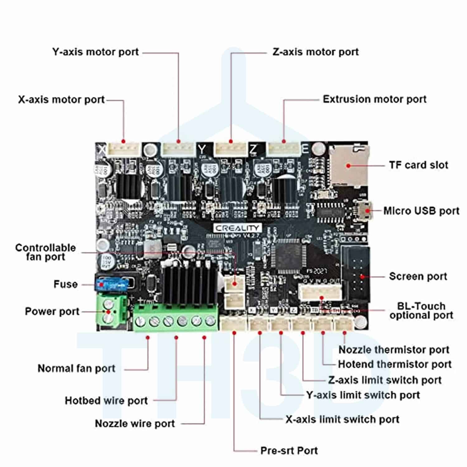
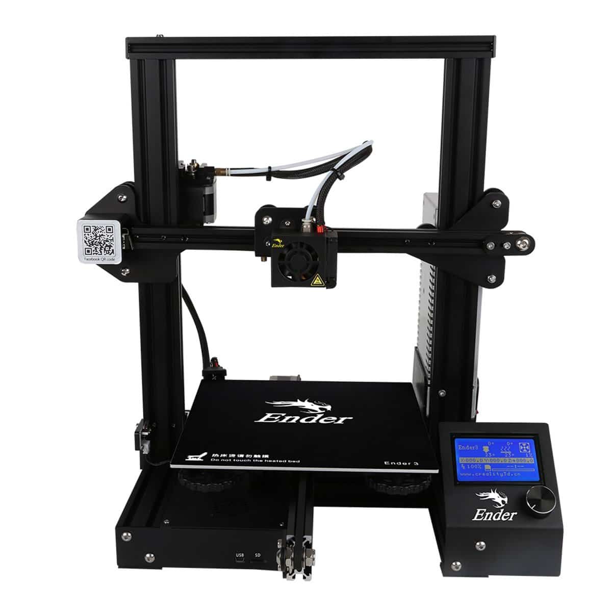
When it comes to wiring your Ender 3 motherboard, it's essential to have a good understanding of its key components and functions. This knowledge will not only help you properly wire your printer, but also troubleshoot any issues that may arise. 1. Mainboard: The mainboard is the heart of your Ender 3 printer.
Duet 2 WiFi on Ender 3 keep LCD Duet3D
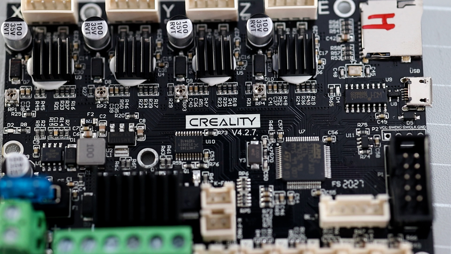
Very cool find here: Ender 3 V2 Schematic for 4.2.2 board · Discussion #814 · Jyers/Marlin · GitHub PDFs also attached here for reference Creality.4.2.2.-.Schematic.28-5-22.pdf (188.1 KB) Creality.4.2.7.-.Schematic.28-5-22-1.pdf (193.7 KB) In addition the 4.2.2 board apparently can come with different driver chips: Creality V4.2.X Board Driver Codes The letters written on the card reader.
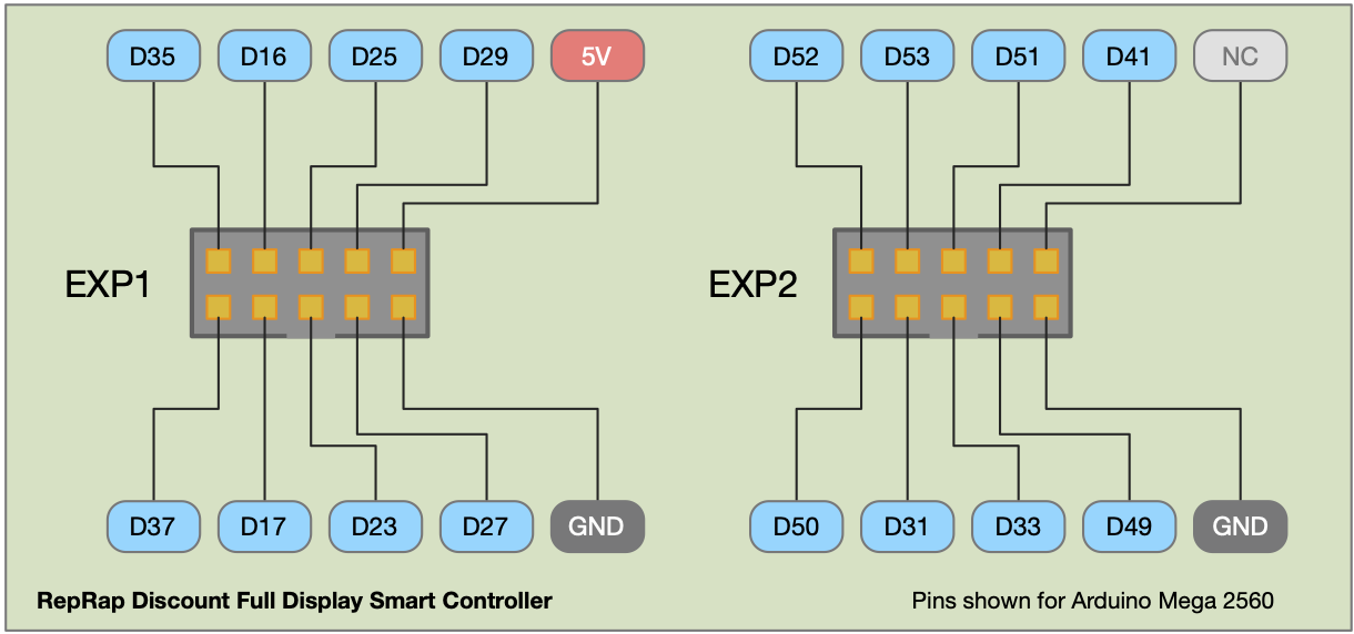
Reprap discount full graphic smart controller распиновка
Creality 12864ZW-10 LCD Display Board for Ender 3 Key Features What's in the box: Display Screen Protect and Support Free 60 Day Tech Support May be returned within 30 days of purchase* Learn More $19.99 Save $15.00 $4.99 18 MINUTE PICKUP Not Available MAP YOUR TRIP Add to List ANYTIME SHIPPING Shipping Not Available

Will SKR mini E3 support Ender 3 V2? · Issue 424 · bigtreetech/BIGTREETECHSKRminiE3 · GitHub
Sort by: Add a Comment. rkNoltem. OP • 2 yr. ago. got it working, here's the config: [display] # RET6 12864 LCD lcd_type: st7920 cs_pin: PB12 sclk_pin: PB13 sid_pin: PB15 encoder_pins: ^PB14, ^PB10 click_pin: ^!PB2. seems the config I had was for the wrong screen model, and the beeper pin was invalid. not sure what pin the beeper should be on.
Creality Ender 3 マザーボード 静音V4.2.7 TMC 割引卸売り archivohistorico.tlaxcala.gob.mx
Hi @sonnius,. It did not look like there was a Klipper log file attached to this ticket. The log file has been engineered to answer common questions the Klipper developers have about the software and its environment (software version, hardware type, configuration, event timing, and hundreds of other questions).
My new Ender 3 mainboard/display run amok r/ender3
If you want to make your Ender 3 printer quieter and more reliable, you might want to consider upgrading to the Creality V4.2.7 silent board. This article will tell you everything you need to know about this mainboard and its features, such as the TMC2225 drivers, the bootloader, and the firmware.

CHPOWER Creality Ender 3 Original LCD Display Board with Ribbon Cable, Ender 3 PRO LCD Display
Feb Instructions to use ender 3 V2 stock LCD with SKR mini E3 V2/V3 or even E3 Turbo. Since Ender 3 V2 & Ender 3 S1 are using the same knob LCD screen, they have slight different pin out compared with the LCD12864 or BTT TFT Screen.
Creality Ender 3 Hurtig Levering & Fri Fragt
¶ Ender-3 S1 Pro User Manual.. Connect the 3-pin (3 wires) 2.0 port to the pinboard, and connect the 3-pin (3 wires) 2.54 port to the filament detector.. The screen display and touch work properly. The movements of the X, Y, and Z axes are smooth. The nozzle and hotbed heat up properly.

Cheapest and Quickest Way to Replace your Ender 3 Motherboard Print3D.World
LCD connector pinout for the Ender-3 V3 SE 7 Sort by: Add a Comment 0xD34D OP • 19 days ago Those of you running klipper might find this useful since the LCD is pretty much useless once you flash klipper. I'm sure y'all can put this to good use.

How to Add an OctoPrint Touchscreen to Your Ender 3 Howchoo
If this post on reddit is accurate, the Ender 3 uses a standard Reprap 12864 LCD module. If you have a breadboard and a 5 volt power source, you can try connecting pin 1 to the power supply and pin 2 to the ground. If the LCD turns on then the issue is most likely with the main board.
Ender 3 v2 How to upgrade firmware (mainboard and screen) Crosslink
Display Corruption - Ender 3 V2/Ender 3 S1/Voxelab Aquila; E1 MaxTemp Error; Extruder Motor will not Turn; Fan Stuck 100% or Not Coming On - Layer Fan or other Fan. MKS SGen L V2 Wiring/Pinouts; SKR E3 Mini V3.0/V3.0.1 Pinout; Dual Z Kits. Dual Z Kit Installation Guide for Ender 3, Ender 3 Pro, Ender 3 V2, CR-20, & Voxelab Aquila.

Flashing Marlin Firmware to the Creality Ender3 Pro — Atechnical Man
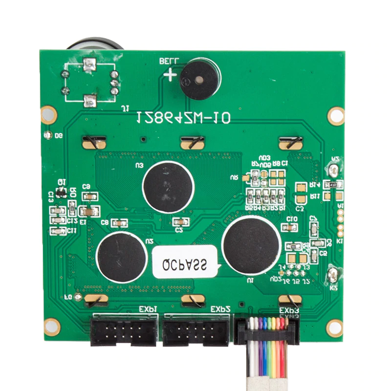
Ender-3 / CR-10 LCD Display Connector pinout The Creality printers are so popular that it is important to support its display controller. Finding pin mappings on the Internet was impossible (They merged 2x 10-pin to 1x 10-pin) Here is the secret undiscovered PIN layout of their connector (The button pins might need a swap) 5V GND SID ?

SKR Mini E3 V2 / V3 on Ender 3 V2 / Ender 3 S1 LCD DWIN Knob Screen Smith3D Malaysia
The Ender 3 display is based on the open Reprap screen design, but includes a header called EXP3 that allows for communication with a single cable. This header communicates with the display over SPI, but the documentation I could find online was sparse and conflicting. I verified the pinout and created this graphic to document this header's.

Creality Ender 3 V2 Silent Mainboard Version 4.2.7 Digitmakers.ca
CatInABearCostume OP • 3 yr. ago • Edited 3 yr. ago I am still getting compile errors, did you successfully do it yourself? EDIT: as of writing, the OEM display of the ender 3 v2 is NOT supported natively by the Marlin firmware. It is supported for other motherboards but the pinout in the common.h does not refer to the OEM display.

HELP! Need help with marlin code to hook up REPRAP discount full graphic smart controller to
Tool kit Steps To Replace The Ender 3 LCD Step 1. Unplug The Printer This seems obvious but I'm stating it anyways. NEVER mess with the electronics of your printer with it plugged in. You could short something and fry the machine, or worse, yourself. Step 2. Disconnect And Remove The LCD From The Printer
